Multimeter Basics: Learn to Measure Like a Pro
- June 13, 2024
- 0 comment
Multimeters might seem intimidating at first, but they are indispensable tools for anyone dealing with electrical systems. By the end of this guide, you’ll not only understand each function of a multimeter but also be able to apply this knowledge effectively. We’ll cover everything from basic measurements to advanced functions and even offer comparisons to help you choose the right multimeter for your needs.
Understanding the Basics
1. Voltage Measurement with a Multimeter
AC (Alternating Current) Measurement
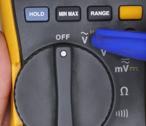
The AC voltage setting on a multimeter is denoted by a wave symbol, reflecting its use in measuring the fluctuating voltages typical of household and commercial power systems. These systems usually operate within a range of 100 to 240 volts, depending on geographical location. To measure AC voltage, set the multimeter to the appropriate AC setting, insert the probes into an electrical outlet (red to one slot, black to another), and read the voltage on the display. This should align with standard values such as 120V or 240V, confirming the outlet’s correct operation and safety.
DC (Direct Current) Measurement
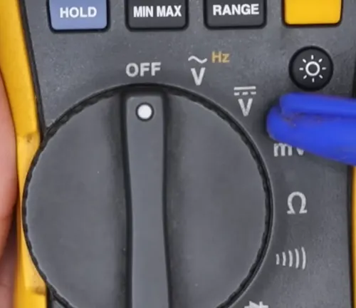
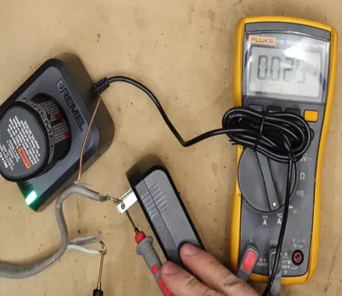
For DC voltage, indicated on the multimeter by a solid line topped with a dotted line, the application is crucial for assessing batteries and other DC-powered devices to ensure they function within specified voltage parameters. To check a battery’s health, for example, switch the multimeter to the DC voltage setting, and attach the red probe to the battery’s positive terminal and the black probe to the negative terminal. A healthy battery will show a voltage reading close to its rated capacity (like 18V or 12V), indicating it is in good working condition.
Example Usage: For a practical example, if you’re testing an 18V battery, after setting your multimeter to measure DC voltage and connecting the probes as described, you should see a reading close to 18 volts on the multimeter’s display. If the voltage is significantly lower, this could indicate the battery is drained or malfunctioning.
Advanced Features and Applications
2. Resistance (Ohms)
Resistance, measured in ohms, quantifies how much a material impedes the flow of electrical current. Materials with low resistance, such as copper, are excellent conductors because they allow electricity to pass through with minimal opposition.
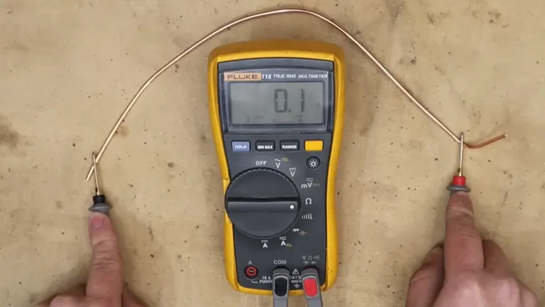
This property makes copper an ideal choice for electrical wiring. On the other hand, materials with high resistance, like rubber, are used as insulators because they significantly restrict the flow of electricity. This characteristic is critical for protecting electrical circuits and operators by preventing unwanted current flow. Thus, understanding and measuring resistance is essential for designing safe and efficient electrical systems.
3. Continuity
Continuity testing is a fundamental and highly useful function of a multimeter that checks if there is a complete path for electrical current to flow through a circuit. This feature is particularly valuable because it provides immediate auditory feedback—a tone—that indicates continuity.
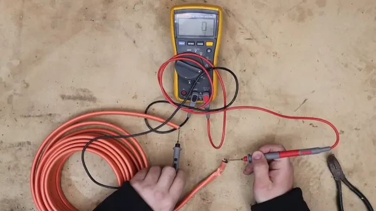
This simplification is crucial when inspecting fuses, switches, and various connectors, as it helps quickly identify breaks or faults in a circuit without visual inspection of each component. For instance, a continuity test can reveal whether a fuse has blown or a switch has malfunctioned, making it a staple in both troubleshooting and regular maintenance checks.
4. Capacitance
Capacitance measurement is crucial for evaluating capacitors, which are components designed to store electrical energy temporarily. This function on a multimeter is used to determine the capacity of a capacitor to hold an electric charge, measured in farad.
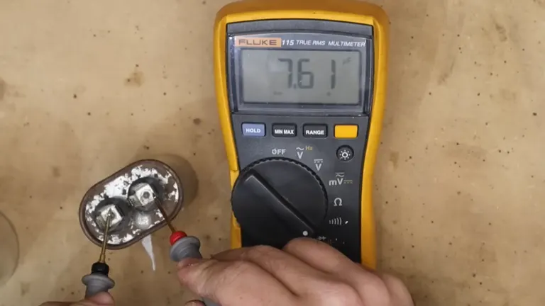
Since capacitors can retain a charge even when disconnected from a power source, handling them requires extra caution to avoid the risk of an electrical shock. When testing capacitors, it’s important to ensure that they are fully discharged before connecting the multimeter. This precaution safeguards both the device and the user, making capacitance testing a critical but sensitive task in the maintenance and repair of electronic circuits.
5. Frequency Measurement (Hertz)
Frequency measurement is a vital function of a multimeter, used to quantify the number of cycles per second in an electrical signal, expressed in hertz (Hz). This measurement is crucial in various applications where maintaining specific frequency standards is essential, such as in power supplies and radio transmissions.
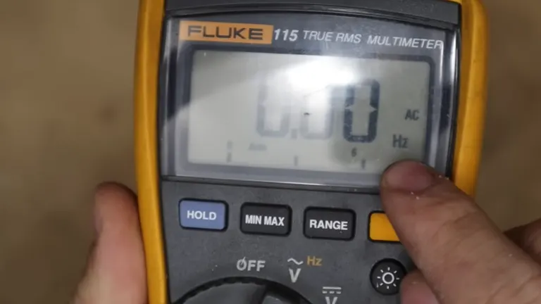
For instance, ensuring that a power supply delivers a consistent frequency is key to the stable operation of electronic devices. Similarly, in radio transmissions, accurate frequency measurement ensures that signals are transmitted and received within designated frequency bands. This capability not only helps in troubleshooting but also in the fine-tuning of electronic circuits to prevent interference and enhance performance.
6. Diode Testing
Diode testing is a crucial feature of a multimeter that checks the functionality of diodes, which are components designed to allow current to flow in only one direction. This testing is essential for ensuring that diodes perform their role effectively within electronic circuits, particularly in power supplies where diodes protect against reverse polarity and manage voltage levels.
During a diode test, the multimeter sends a small current through the diode and measures the voltage drop across it. A properly functioning diode will show a low voltage drop in the forward direction (typically 0.6 to 0.7 volts for silicon diodes) and a high resistance in the reverse direction, indicating no current flow. This simple test helps confirm the health and operability of diodes, safeguarding the overall integrity of electronic devices.
Special Functions
7. Temperature Measurement
Some multimeters come equipped with the capability to measure temperature, a feature particularly valuable in environments where temperature monitoring is crucial for system stability and efficiency. This function typically requires a separate probe that can be connected to the multimeter. Once attached, the probe can measure either surface or ambient temperatures, depending on the probe’s design.
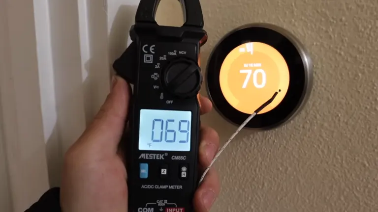
This is particularly useful in applications such as HVAC systems, engine diagnostics, and electronic device maintenance, where understanding temperature variations is essential for preventing overheating and ensuring optimal performance. By integrating temperature measurement, multimeters provide a more comprehensive diagnostic tool that extends beyond electrical parameters.
8. Amperage Measurement
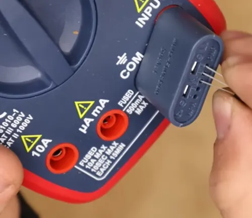
Amperage measurement is a crucial function of a multimeter, used to determine the current flowing through a circuit. There are two primary methods for measuring current:
Series Method
This traditional method requires integrating the multimeter directly into the circuit. To accomplish this, the circuit must be opened, and the multimeter inserted in series with the circuit components. While this method can provide very accurate measurements, it carries inherent risks, including the potential for short circuits or exposure to high voltages. It is vital to ensure all safety precautions are adhered to and the circuit is powered down before inserting the multimeter.
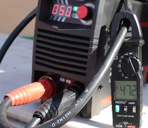
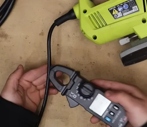
Clamp Method
The clamp method offers a safer alternative that does not require direct contact with the circuit’s conductive parts. By using a clamp meter, you can measure the current by simply clamping the meter around a single wire. This method is not only safer, reducing the risk of electrical shock and circuit damage, but also quicker, as it does not require the circuit to be powered down or opened. Clamp meters work by measuring the magnetic field around a conductor, converting it to a current reading without any physical connection to the electrical conductors.
Both methods have their applications, with the series method being suitable for low-current measurements where high accuracy is required, and the clamp method being ideal for quick diagnostics and measurements in higher-current settings.
9. Other Functions
Advanced multimeters go beyond basic measurements, incorporating a variety of specialized functions that enhance their utility in complex electronics diagnostics and repairs. Here are some notable additional features:
Transistor Testing
This function allows for the evaluation of transistors, which are fundamental components in most electronic devices. Transistor testing helps determine the health and characteristics of these components, such as their gain and response behaviors. It typically involves using a special socket or adapter on the multimeter where the transistor leads are inserted to measure their properties.
Duty Cycle Measurements
The duty cycle of a signal refers to the proportion of time a signal is ‘on’ versus ‘off’ within a given period. Measuring the duty cycle is crucial in applications involving pulse-width modulation, where the efficiency of power transfer and signal integrity often hinge on precise duty cycle settings. This function is particularly useful in the automotive and telecommunications industries.
Non-Contact Voltage Detection (NCV)
Non-contact voltage detection allows electricians and technicians to detect voltage in wires and electrical devices without direct contact. By simply bringing the multimeter close to a conductor, users can determine if it is live, which enhances safety by reducing the risk of electric shock. This feature is especially valuable in preliminary inspections and quick checks.
Safety Precautions for Multimeter Use
Safety is paramount when operating a multimeter, particularly when measuring high voltages or currents. Here are key safety guidelines to ensure proper usage and prevent accidents:
- Before connecting the probes, always ensure the multimeter is set to the appropriate function and range. This avoids misreading and potential damage to the multimeter.
- To minimize the risk of electric shock that could result from the current passing through the heart, use one hand to operate the multimeter when possible. Keep the other hand away from the equipment to avoid creating a path for current through your body.
- Always check the voltage and current ratings on the multimeter and ensure not exceed them. Using the multimeter on settings higher than its capacity can lead to serious injury or damage the device.
Choosing the Right Multimeter
Selecting the right multimeter involves understanding the specific needs of your projects or tasks:
- Consider the tasks for which you need the multimeter. If you’re dealing with basic electrical issues, a standard multimeter with voltage, current, and resistance might suffice. For more complex diagnostics involving capacitors, transistors, or frequency measurements, a more advanced model is necessary.
- Auto-ranging multimeters are user-friendly as they automatically adjust to the correct range based on the detected signal. They are ideal for beginners or for convenience in fast-paced environments. Manual ranging multimeters, while generally cheaper, require you to select the measurement range yourself, which can be beneficial for learning purposes or specific professional tasks.
- For accurate readings in non-standard waveforms, such as those in variable speed motor drives or computer power supplies, a True RMS multimeter is crucial. True RMS models provide a more accurate depiction of complex signals by factoring in variations in the AC waveform, essential for precise troubleshooting in modern electronic applications.
Conclusion
With a proper understanding of its features and safe usage practices, a multimeter can be an incredibly powerful tool in both troubleshooting and building electrical systems. Whether you are a hobbyist, student, or professional, the right multimeter can make all the difference in your electrical projects. Remember, the key to effective electrical measurement lies in understanding the capabilities of your tool and applying them safely and accurately.
FAQs
- How can I tell if my multimeter is accurate?
To test the accuracy of a multimeter, use it to measure a known voltage or resistance. For voltage, a standard household battery (like a 1.5V AA battery) is a good test object. Compare the multimeter’s reading with the expected value. If the readings are off, calibration or repair may be needed. - Can a multimeter be used to test any type of electrical appliance?
Multimeters can be used to test a wide range of electrical devices, from small batteries to household appliances. However, the capacity to test certain appliances depends on the multimeter’s specifications, especially the maximum voltage and current it can safely measure. - What is the significance of a multimeter’s CAT rating?
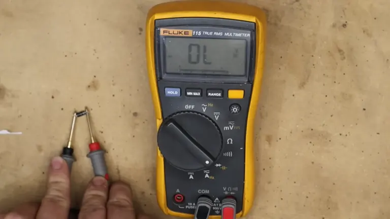
The CAT (Category) rating on a multimeter indicates its safety level for use in different electrical environments. CAT I is for protected electronic circuits, CAT II for appliances connected to residential circuits, CAT III for industrial and commercial building circuits, and CAT IV for utility connections at the building’s service entrance. - Why does my multimeter display ‘OL’ or ‘1’ during resistance measurements?
‘OL’ or ‘1’ on the display indicates that the resistance being measured is out of the multimeter’s range, suggesting an open circuit or overload condition. This might occur if the circuit is broken or the resistance is too high for the chosen range. - Is it dangerous to measure capacitance directly in an active circuit?
Yes, measuring capacitance directly in an active circuit can be dangerous and may lead to incorrect readings or damage the multimeter. Always ensure that the capacitors are fully discharged and isolated from any power source before measuring their capacitance.
We hope this guide has illuminated the versatile world of multimeters for you! If you have any experiences or tips to share about using multimeters, or if there’s something you’re curious about that we didn’t cover, please drop a comment below. Your insights not only help us improve but also enrich our community’s knowledge. Happy measuring!

David Murray
Forestry AuthorI'm David Murry, a forestry equipment specialist with a focus on chainsaw operation. With over 13 years of experience, I've honed my skills in operating and maintaining a wide range of machinery, from chainsaws to log splitters. My passion for the outdoors and commitment to sustainable forestry drive my work, which emphasizes safety, efficiency, and staying updated with industry advancements. Additionally, I'm dedicated to sharing my expertise and promoting environmental awareness within the forestry community.


Leave your comment